meta data for this page
This is an old revision of the document!
General info
ESP8266 is a SOC module contains:
- CPU: Tensilca Xtensa LX3, 32bit, 80MHz
- RAM: 32kB, DRAM 80kB, Flash 200kB
- WiFi 802.11 b/g/n (soft AP mode available)
- and more
Additionally on PCB:
- External SPI Flash 512kB with firmware
Device is 3,3V only and can consume over 200mA. Some FTDI or PL2303 conventers are capable to provide 3,3V VCC but the power is not enough to provide stable supply.

Memory MAP: http://www.esp8266.com/wiki/doku.php?id=esp8266_memory_map
esp8266_specifications_english.pdf
0a-esp8266_datasheet_en_v4.3.pdf
Modules versions
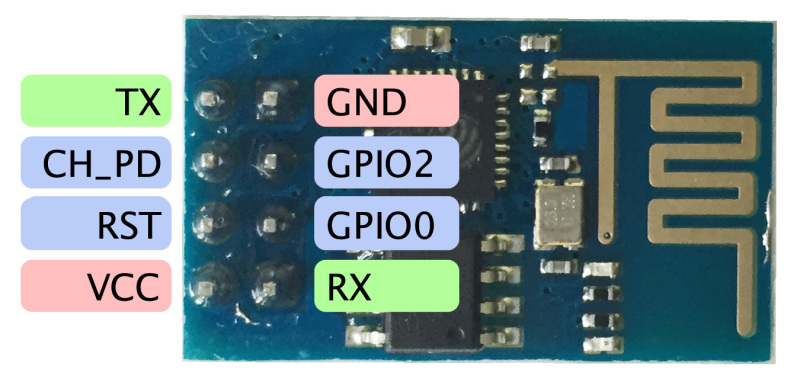
ESP-01
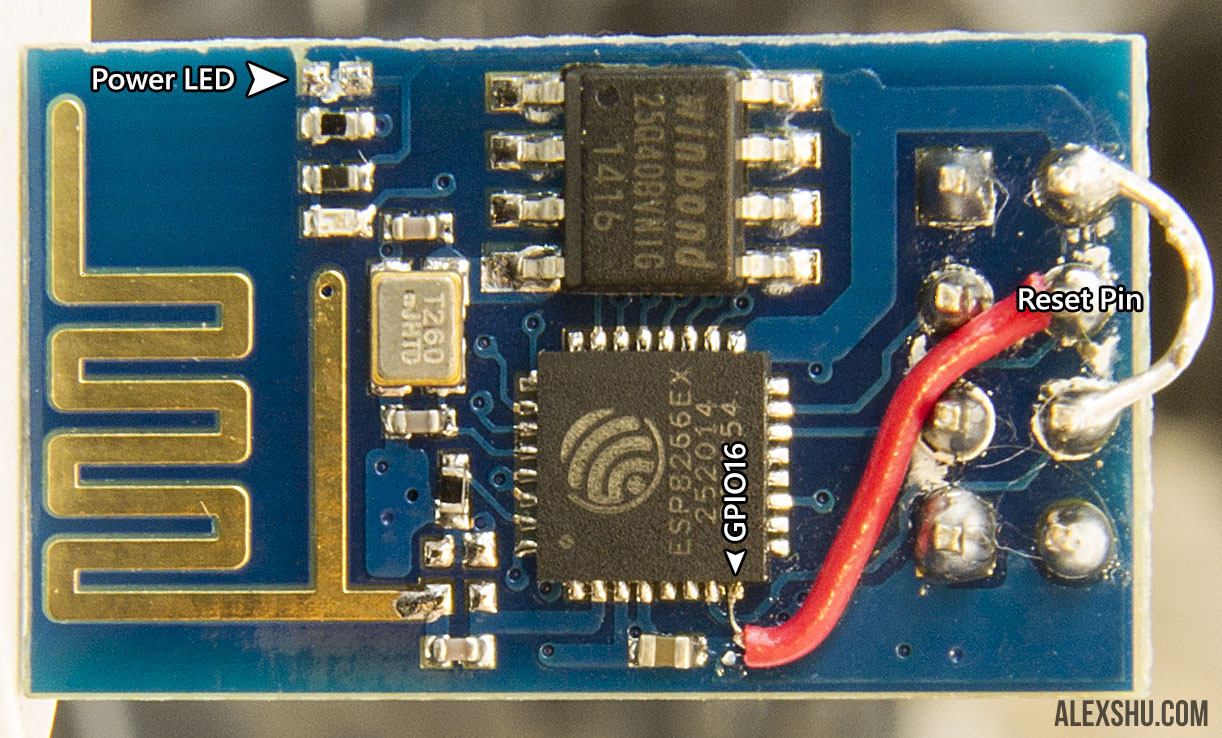
To enable deep sleep mode, connect XPD pin to RESET pin (picture from http://www.esp8266.com/viewtopic.php?f=32&t=5701&start=28)
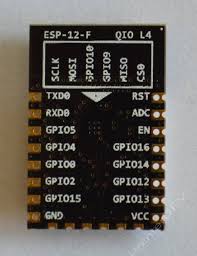
ESP-12
ESP-12E

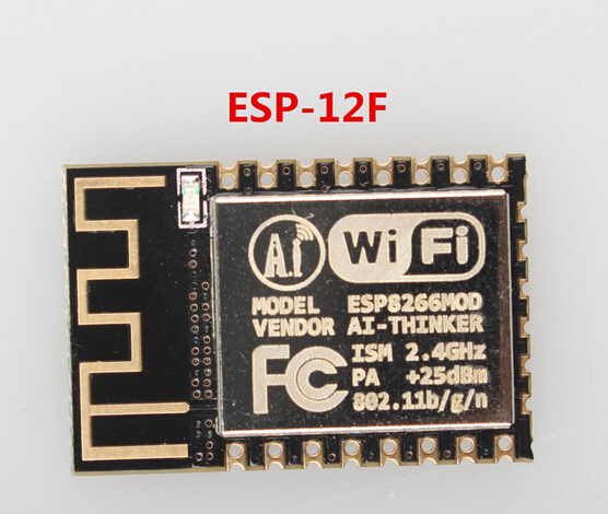
ESP-12F
improved stability, better antenna, 4 layer pcb.
ESP-14
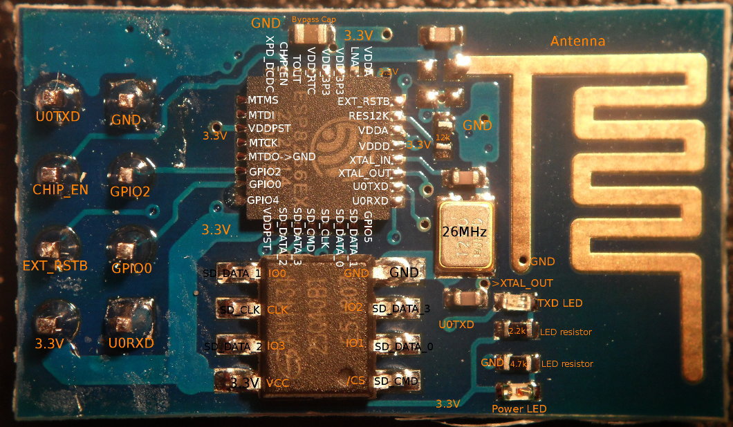
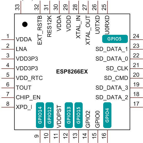
Pinout
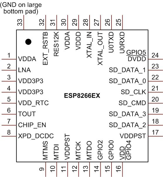
| Pin # | GPIO | role / description | |||
|---|---|---|---|---|---|
| 7 | CH_PD | CHIP_EN | Chip power down - to enable chip needs to be pulled up | ||
| 32 | EXT_RSTB | External reset signal (active low) | |||
| 6 | T_OUT | ADC | |||
| 15 | GPIO0 | FLSH | SPI_CS2 | Pull up during powering to go into flashing mode | |
| 26 | GPIO1 | UART0_TXD | SPI_CS1 | Uart Tx during flash programming | 3,3V ! |
| 14 | GPIO2 | UART Tx during flash programming | |||
| 25 | GPIO3 | UART0_RXD | Uart Rx during flash programming | 3,3V ! | |
| 16 | GPIO4 | ||||
| 24 | GPIO5 | ||||
| 21 | GPIO6 | SPI_CLD | SD_CLK | ||
| 22 | GPIO7 | SPI_MISO | SD_D0 | ||
| 23 | GPIO8 | SPI_MOSI | SD_D1 | ||
| 18 | GPIO9 | HSPI_HD | SPI_HD | SD_D2 | |
| 19 | GPIO10 | HSPI_WP | SPI_WP | SD_D3 | |
| 20 | GPIO11 | SPI_CS0 | SD_CMD | ||
| 10 | GPIO12 | HSPI_MISO | MTDI | ||
| 12 | GPIO13 | HSPI_MOSI | UART0_CTS | ||
| 9 | GPIO14 | HSPI CLK | MTMS | ||
| 13 | GPIO15 | HSPI CS | MTDO | UART0_RTS | |
| 8 | GPIO16 | XPD_DCDC | Depp sleep Timer output / USER / WAKE | ||
| 11 | VDDPST | Digital I/O Power Supply (1.8V~3.3V) | |||
| 17 | VDDPST | Digital I/O Power Supply (1.8V~3.3V) | |||
| 29 | VDD | Analog power 3.0V~3.6V | |||
| 30 | VDDA | Analog power 3.0V~3.6V | |||
| 27 | XTAL_OUT | ||||
| 28 | XTAL_IN | ||||
| 31 | RES12K | Serial connection with a 12kOhm resistor do ground |
Flashing new firmware
When Chip is powered on, with GPIO0 pulled up, it enter into firmware downloading mode.
esptool
Download/clone https://github.com/themadinventor/esptool
Example usage:
./esptool.py --port /dev/ttyUSB1 --baud 9600 write_flash 0 ../nodemcu_float_0.9.6-dev_20150704.bin
Connecting...
Erasing flash...
Writing at 0x00001400... (1 %)
Erasing flash...
Wrote 462848 bytes at 0x00000000 in 520.5 seconds (7.1 kbit/s)...

Leaving...
Firmwares
Own firmware in C
AT command
NodeMCU
It is LUA based firmware (command interpreter). https://github.com/nodemcu/nodemcu-firmware
NodeLua
ESP Easy
The ESP Easy firmware can be used to turn the ESP module into an easy multifunction sensor device for Home Automation solutions like Domoticz. Configuration of the ESP Easy is entirely web based, so once you've got the firmware loaded, you don't need any other tool besides a common web browser. http://www.esp8266.nu
Wiki page ESP Easy